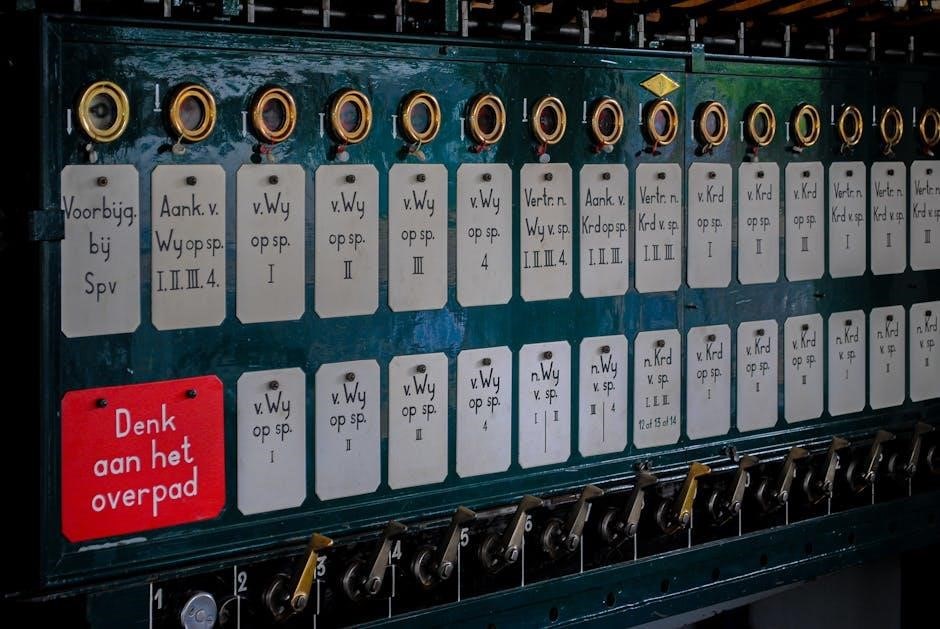
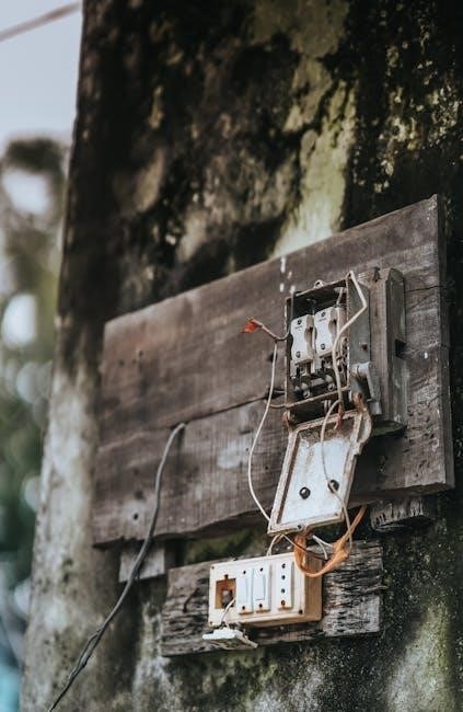
An electrical panel wiring diagram is a visual representation of an electrical panel’s components and connections‚ aiding in installation‚ troubleshooting‚ and ensuring compliance with safety standards.
1.1 Definition and Purpose
An electrical panel wiring diagram is a detailed visual representation of the components and connections within an electrical panel‚ serving as a blueprint for installation‚ maintenance‚ and troubleshooting. Its purpose is to provide a clear understanding of how devices are interconnected‚ ensuring safe and efficient electrical system operation while adhering to regulatory standards.
1.2 Importance of Wiring Diagrams in Electrical Systems
Wiring diagrams are indispensable for understanding electrical systems‚ ensuring safe and efficient installations‚ and facilitating troubleshooting. They provide clarity for electricians‚ helping identify components and connections‚ and ensure compliance with safety standards. These diagrams are crucial for preventing errors during maintenance and upgrades‚ ultimately safeguarding the reliability and functionality of electrical systems.
Key Components of an Electrical Panel Wiring Diagram
An electrical panel wiring diagram includes key components such as circuit breakers‚ fuses‚ transformers‚ terminal blocks‚ and wiring‚ ensuring safe and efficient electrical system management.
2.1 Power Devices (Circuit Breakers‚ Fuses)
Power devices like circuit breakers and fuses protect electrical systems from overcurrent. Circuit breakers open during surges‚ while fuses melt to interrupt the flow. These devices are essential for safety and are clearly represented in wiring diagrams‚ ensuring proper installation and maintenance. For example‚ a MicroLogix PLC system may use fuses to protect variable frequency drives‚ as shown in the diagram.
2.2 Control Devices (Programmable Logic Controllers‚ Variable Frequency Drives)
Control devices such as Programmable Logic Controllers (PLCs) and Variable Frequency Drives (VFDs) are central to modern electrical panels. PLCs manage automation processes‚ while VFDs regulate motor speeds. In diagrams‚ these devices are detailed with inputs and outputs‚ ensuring precise connections. For instance‚ a MicroLogix PLC might connect to external I/O modules‚ as illustrated in the wiring diagram‚ to control industrial machinery efficiently.
2.3 Transformers and Power Supplies
Transformers and power supplies are essential for voltage regulation within electrical panels. Transformers convert voltage levels‚ such as 575VAC to 115VAC‚ ensuring compatibility with devices like PLCs and HMIs. Power supplies provide stable DC voltage for controls. Both are represented with distinct symbols in wiring diagrams‚ highlighting their roles in managing power distribution and ensuring system stability across different voltage requirements.
2.4 Terminal Blocks and Wiring
Terminal blocks and wiring are critical for connecting electrical components. Terminal blocks serve as centralized connection points‚ organizing wires for easy access. Wires are represented as lines in diagrams‚ with junctions indicating connections between multiple conductors. Proper wiring ensures safe and efficient power distribution‚ while clear labeling aids in maintenance and troubleshooting‚ adhering to standards for system reliability and compliance.

Regulatory Standards for Electrical Panels
Electrical panels must comply with national and local codes‚ such as the NEC‚ ensuring safety‚ efficiency‚ and legal adherence in design and installation.
3.1 National Electrical Code (NEC) Compliance
The National Electrical Code (NEC) sets mandatory standards for electrical installations‚ ensuring safety and efficiency. Compliance with NEC is crucial for electrical panels‚ covering wiring methods‚ circuit protection‚ and grounding. Adherence prevents hazards‚ meets legal requirements‚ and guarantees reliable system performance. Regular updates reflect technological advancements‚ making NEC compliance essential for all electrical panel designs and installations.
3.2 Local Authority Requirements
Local authority requirements supplement the NEC‚ tailoring standards to regional conditions. These rules address unique environmental or structural challenges. Compliance ensures panels meet area-specific safety and efficiency standards‚ adapting to local regulations. Authorities may enforce additional inspections or permit processes‚ ensuring installations align with community needs and safety expectations. Adhering to these requirements is vital for legal and operational compliance.

How to Read an Electrical Panel Wiring Diagram
Understanding an electrical panel wiring diagram involves identifying components and their connections. This skill is essential for troubleshooting‚ maintenance‚ and ensuring the system operates safely and efficiently.
4.1 Step-by-Step Guide to Interpreting the Diagram
Start by identifying the main components‚ such as circuit breakers and transformers. Trace connections between devices to understand power flow. Verify terminal labels and ensure all symbols match standard conventions. Check voltage levels and cross-reference with the system’s specifications. This systematic approach ensures accurate interpretation and safe electrical system operation‚ helping to identify potential issues efficiently.
4.2 Understanding Symbols and Conventions
Electrical panel wiring diagrams use standardized symbols to represent components like circuit breakers‚ transformers‚ and terminals. Understanding these symbols is crucial for interpreting the diagram accurately. Conventions such as line styles and color coding differentiate between power‚ control‚ and grounding wires. Familiarizing yourself with these symbols and conventions ensures clarity and helps in identifying connections and pathways within the electrical system efficiently.

Wiring an Electrical Panel: A Simplified Guide
Start by planning the layout‚ ensuring proper spacing and organization. Install circuit breakers‚ transformers‚ and terminal blocks‚ then connect wires systematically‚ ensuring safety and compliance with diagrams.
5.1 Planning the Layout
Planning the layout is crucial for efficient wiring. Start by identifying the panel’s purpose and required components. Use the wiring diagram to map device locations‚ ensuring proper spacing and organization. Consider power devices‚ transformers‚ and control systems‚ and plan for future scalability. Labeling and clear pathways for wires are essential for easy maintenance and compliance with safety standards.
5;2 Installing and Connecting Components
Install components according to the wiring diagram‚ ensuring secure mounting. Connect power devices‚ transformers‚ and control systems carefully. Use appropriate tools and follow safety protocols. Verify connections for accuracy and test circuits before energizing. Proper installation ensures reliability and safety‚ minimizing future issues and adherence to electrical codes. Always refer to the diagram for precise wiring instructions.
Safety Devices and Interlocking Mechanisms
Safety devices like circuit breakers and fuses protect against overcurrent‚ while interlocking mechanisms ensure proper sequence of operations. These components prevent hazards and maintain system integrity‚ ensuring safe operation.
6.1 Role of Circuit Breakers and Fuses
Circuit breakers and fuses are essential safety devices in electrical panels. They detect overcurrent conditions‚ such as short circuits or overloads‚ and interrupt the flow of electricity to protect the system from damage. Fuses melt when excessive current is detected‚ while circuit breakers trip open to halt power. Both ensure the electrical system remains safe and operational‚ preventing potential hazards and downtime. Proper selection and installation of these devices are critical for reliable performance and compliance with safety standards‚ as specified in wiring diagrams.
6.2 Emergency Stop Buttons and Limit Switches
Emergency stop buttons and limit switches are critical safety components in electrical panels. Emergency stops immediately interrupt power to machinery in dangerous situations‚ while limit switches monitor mechanical movements and prevent operations beyond set boundaries. Both devices are essential for safeguarding personnel and equipment. Their connections are clearly detailed in wiring diagrams‚ ensuring rapid response and adherence to safety protocols. Proper installation and testing are vital for reliable operation. These devices prevent accidents and downtime‚ ensuring compliance with industrial safety standards. Their activation or deactivation triggers specific responses‚ maintaining system integrity and operator security. Regular maintenance of these components is crucial for continuous safe operation. By integrating them into the electrical panel‚ they provide an additional layer of protection and control‚ enhancing overall system reliability and safety. Their inclusion in wiring diagrams ensures easy identification and troubleshooting‚ making them indispensable in industrial settings. Proper labeling and clear representation in diagrams facilitate quick responses during emergencies‚ minimizing risks and ensuring smooth operations. These safety mechanisms are fundamental to modern electrical systems‚ protecting both equipment and personnel from potential hazards. Their role in maintaining operational safety cannot be overstated‚ making them a cornerstone of electrical panel design and functionality. By understanding their functions and connections‚ technicians can ensure optimal performance and adherence to safety standards. This ensures that electrical systems operate efficiently while prioritizing safety‚ which is essential in any industrial or commercial setting. Regular inspections and updates to these components are necessary to uphold safety protocols and prevent unforeseen issues. Their strategic placement and integration into the wiring diagram highlight their importance in overall system design. As such‚ emergency stop buttons and limit switches remain vital elements in maintaining the safety and efficiency of electrical systems. Their proper implementation and maintenance are key to preventing accidents and ensuring uninterrupted operations. By following the guidelines outlined in wiring diagrams‚ technicians can ensure these devices function as intended‚ providing a secure and reliable electrical environment. This not only protects equipment but also ensures the well-being of individuals working with or around the electrical systems. In summary‚ emergency stop buttons and limit switches are essential components that enhance safety and reliability in electrical panels‚ as clearly illustrated in wiring diagrams. Their inclusion and proper setup are critical for maintaining operational integrity and safety standards in any electrical system.
Voltage Regulation and Management
Voltage regulation ensures stable power supply by converting and managing different voltage levels using transformers and power supplies‚ essential for maintaining system performance and safety standards.
7.1 Transformers and Power Supplies
Transformers and power supplies are essential for voltage regulation‚ converting voltage levels to meet system requirements. Transformers adjust AC voltage‚ while power supplies stabilize DC voltage. These components ensure compatibility between devices‚ preventing damage from voltage mismatches. Their proper sizing and connection are critical‚ as shown in wiring diagrams‚ which detail their placement and connections to maintain safe and efficient operation.
7.2 Managing Different Voltage Levels
Managing various voltage levels in an electrical panel ensures components operate safely and efficiently. Wiring diagrams clearly indicate separate terminals‚ fuses‚ and wiring gauges for each voltage level. Tracing connections back to their source helps confirm specifications‚ as voltage levels are typically noted at the source rather than each conductor‚ maintaining clarity and preventing potential hazards in the system.
Control Devices and Their Representation
Control devices like PLCs and VFDs are crucial for automation. Their representation in wiring diagrams includes detailed symbols and connections‚ ensuring precise communication of their roles in the system.
8.1 Programmable Logic Controllers (PLCs)
Programmable Logic Controllers (PLCs) are the brain of modern electrical systems‚ enabling automation and control. They process inputs from sensors and outputs to devices‚ using power supplies and I/O modules. In wiring diagrams‚ PLCs are shown with detailed connections‚ often including specific models like MicroLogix. Their representation ensures precise communication of their roles‚ adhering to standards like NEC for safe and efficient operation.
8.2 Variable Frequency Drives (VFDs)
Variable Frequency Drives (VFDs) regulate motor speed by adjusting frequency and voltage‚ enhancing energy efficiency. In wiring diagrams‚ VFDs are depicted with detailed connections to motors‚ PLCs‚ and power supplies. Their representation includes specific symbols‚ ensuring clear communication of their integration and control functions within the electrical panel‚ adhering to standards like NEC for safe and efficient operation.
Best Practices for Wiring Diagrams
Use clear labeling‚ standard symbols‚ and logical layouts. Ensure consistency and avoid clutter. Follow safety standards and update diagrams regularly for accuracy and compliance.
9.1 Clear Labeling and Organization
Clear labeling and organization are essential for readability. Use standard symbols and consistent color coding for wires. Label every component and connection clearly. Avoid clutter by grouping related elements. Ensure diagrams are logically structured‚ making it easy to trace circuits. Cross-reference components for quick identification. This ensures efficiency and reduces errors during installation and troubleshooting.
9.2 Avoiding Common Mistakes
Ensure accuracy by double-checking wire colors and component labels. Avoid overcrowding diagrams‚ as this can lead to confusion. Use consistent symbols and notation throughout. Verify that all connections align with the intended circuit logic. Neglecting these steps can result in safety hazards or system malfunctions. Always cross-reference with manufacturer specifications and comply with NEC standards to minimize errors.

Advanced Topics in Panel Wiring
Advanced panel wiring involves network integration‚ scalability‚ and future-proofing electrical systems. These topics ensure systems adapt to evolving technologies and manage complex connections efficiently‚ enhancing overall performance and reliability.
10.1 Network Integration and Protocols
Network integration in electrical panels involves embedding communication protocols like EtherNet‚ DeviceNet‚ and ProfiBUS. These protocols enable data exchange between devices‚ ensuring efficient system operation. Diagrams simplify multi-conductor cables as single lines‚ focusing on connectivity rather than physical wiring details. Understanding these protocols is crucial for modern‚ scalable‚ and interoperable electrical systems‚ enhancing performance and adaptability in industrial applications;
10.2 Scalability and Future-Proofing
Scalability ensures electrical panels adapt to evolving demands by incorporating modular designs and standardized components. Future-proofing involves selecting devices and layouts that accommodate emerging technologies and protocols. This approach minimizes redesign efforts and allows seamless integration of new devices‚ ensuring the system remains efficient and up-to-date with advancing electrical standards and requirements over time.
Troubleshooting Electrical Panel Issues
Electrical panel wiring diagrams are essential for identifying and resolving issues like short circuits‚ overloaded circuits‚ or faulty connections‚ ensuring safe and efficient system operation.
11.1 Using Diagrams to Identify Faults
Electrical panel wiring diagrams provide a clear visual map of connections‚ enabling technicians to trace wires‚ identify faulty components‚ and detect issues like short circuits or overloads. By referencing the diagram‚ professionals can pinpoint where a malfunction occurs‚ ensuring precise troubleshooting and minimizing downtime. This systematic approach prevents guesswork and ensures repairs are both efficient and safe.
11.2 Common Issues and Solutions
Common issues in electrical panels include short circuits‚ overloaded circuits‚ and faulty circuit breakers. Solutions involve inspecting wiring for damage‚ redistributing load to prevent overloads‚ and replacing defective components. Regular maintenance‚ such as tightening connections and upgrading outdated systems‚ can prevent recurring problems and ensure safe‚ reliable operation of the electrical system.
Understanding electrical panel wiring diagrams is crucial for safe and efficient management of electrical systems. They are key to effective installation‚ proper maintenance‚ and troubleshooting.
12.1 Summary of Key Concepts
Electrical panel wiring diagrams are essential for understanding and managing electrical systems. They outline components‚ connections‚ and safety protocols‚ ensuring compliance with standards like NEC. Proper interpretation aids in installation‚ troubleshooting‚ and maintenance‚ while best practices enhance clarity and organization. These diagrams are vital for electricians and technicians‚ providing a clear roadmap for system operations and modifications.
12.2 Final Thoughts on the Importance of Wiring Diagrams
Electrical panel wiring diagrams are indispensable for safe and efficient system management. They simplify complex electrical setups‚ ensuring adherence to safety standards and facilitating troubleshooting. By providing a clear visual guide‚ these diagrams empower electricians and technicians to maintain‚ upgrade‚ and repair electrical systems with confidence and precision‚ making them a cornerstone of modern electrical practices.
